Instead of starting with a mesh in local space, we are starting with a 2d mouse cursor position in viewport space. We work backwards through the transformation by using inverse matrices, and arrive with a ray in world space.
It can be useful to click on, or "pick" a 3d object in our scene using the mouse cursor. One way of doing this is to project a 3d ray from the mouse, through the camera, into the scene, and then check if that ray intersects with any objects. This is usually called ray casting. This is an entirely mathematical exercise - we don't use any OpenGL code or draw any graphics - this means that it will apply to any 3d application the same way. The mathematical subject is usually called geometric intersection testing.
With ray picking we usually simplify a scene into bounding spheres or boxes. This makes the calculation a bit easier than testing all of the individual triangles. We don't need to create a 3d sphere out of triangles that can be rendered; we just represent the sphere as a simple function. The premise is that we have a mathematical formula for the points along a ray, and a mathematical formula for the points on a sphere. If we substitute the points on the sphere with the equation for points on a ray, then we get the intersection of points that are common to both. It's interesting to do this technique now because it shows us how we can use the transformation pipeline in reverse; from 2d screen to a 3d world space by using the inverse of our matrices e.g ...inverse(view_matrix) * inverse(projection_matrix).... In a later tutorial we will look at an alternative technique using unique colours to determine where the mouse is hovering or clicking.
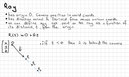
All ray casting starts with a ray. In this case it has an origin O at the position of the camera. We can do ray intersections in any space (world, eye, etc.), but everything needs to be in the same space - let's assume that we are doing our calculations in world space. This means that our ray origin is going to be the world x,y,z position of the camera.
range [0:width, height:0]
We are starting with mouse cursor coordinates. These are 2d, and in the viewport coordinate system. First we need to get the mouse x,y pixel coordinates. You might have set up a call-back function (with e.g. GLFW or GLUT) something like this:
void mouse_click_callback(int b, int s, int mouse_x, int mouse_y);
This gives us an x in the range of 0:width and y from height:0. Remember that 0 is at the top of the screen here, so the y-axis direction is opposed to that in other coordinate systems.
range [-1:1, -1:1, -1:1]
The next step is to transform it into 3d normalised device coordinates. This should be in the ranges of x [-1:1] y [-1:1] and z [-1:1]. We have an x and y already, so we scale their range, and reverse the direction of y.
float x = (2.0f * mouse_x) / width - 1.0f;
float y = 1.0f - (2.0f * mouse_y) / height;
float z = 1.0f;
vec3 ray_nds = vec3(x, y, z);
We don't actually need to specify a z yet, but I put one in (for the craic).
range [-1:1, -1:1, -1:1, -1:1]
We want our ray's z to point forwards - this is usually the negative z direction in OpenGL style. We can add a w, just so that we have a 4d vector.
vec4 ray_clip = vec4(ray_nds.xy, -1.0, 1.0);
Note: we do not need to reverse perspective division here because this is a ray with no intrinsic depth. Other tutorials on ray-casting will, incorrectly, tell you to do this. Ignore the false prophets! We would do that only in the special case of points, for certain special effects.
range [-x:x, -y:y, -z:z, -w:w]
Normally, to get into clip space from eye space we multiply the vector by a projection matrix. We can go backwards by multiplying by the inverse of this matrix.
vec4 ray_eye = inverse(projection_matrix) * ray_clip;
Now, we only needed to un-project the x,y part, so let's manually set the z,w part to mean "forwards, and not a point".
ray_eye = vec4(ray_eye.xy, -1.0, 0.0);
range [-x:x, -y:y, -z:z, -w:w]
Same again, to go back another step in the transformation pipeline. Remember that we manually specified a -1 for the z component, which means that our ray isn't normalised. We should do this before we use it.
vec3 ray_wor = (inverse(view_matrix) * ray_eye).xyz;
// don't forget to normalise the vector at some point
ray_wor = normalise(ray_wor);
This should balance the up-and-down, left-and-right, and forwards components for us. So, assuming our camera is looking directly along the -Z world axis, we should get [0,0,-1] when the mouse is in the centre of the screen, and less significant z values when the mouse moves around the screen. This will depend on the aspect ratio, and field-of-view defined in the view and projection matrices. We now have a ray that we can compare with surfaces in world space.
If you're happy with this theory then you can condense all of these instructions into one line.
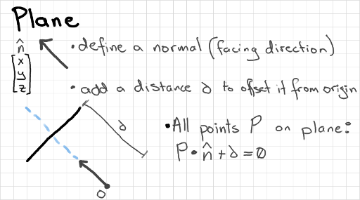
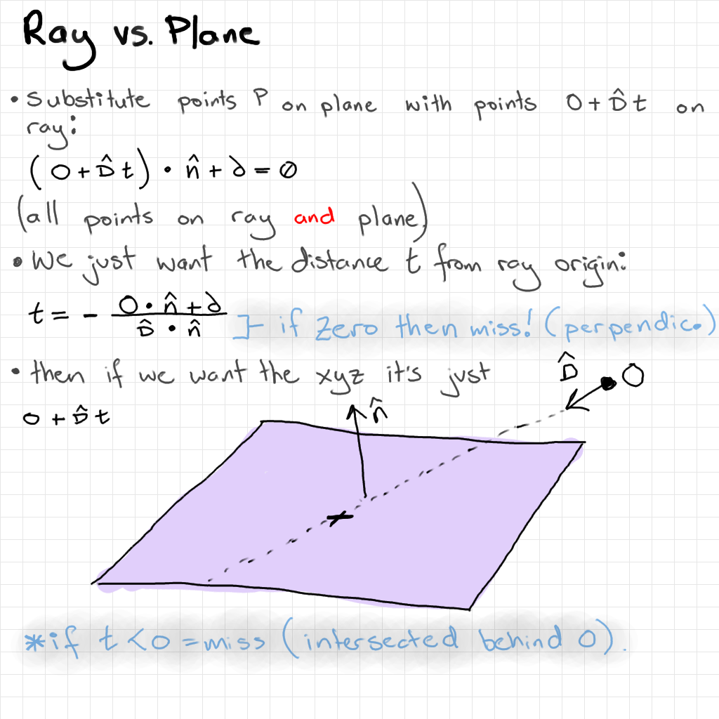
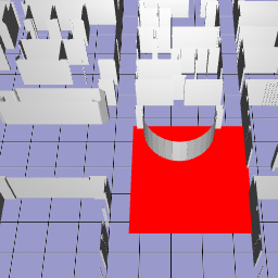
We can describe any surface as a plane. It's often useful to do this before doing more detailed (and more computationally expensive) intersection tests. We can test, for example, if a point is inside a region bounded by planes - if not, then no need to check versus individual triangles inside the region. In my case, I wanted to create an imaginary ground plane that I could use to help me click-and-drag boxes around scenery. I do 2 ray-plane intersections to get the top-left and bottom-right corners of the box in xyz world coordinates.
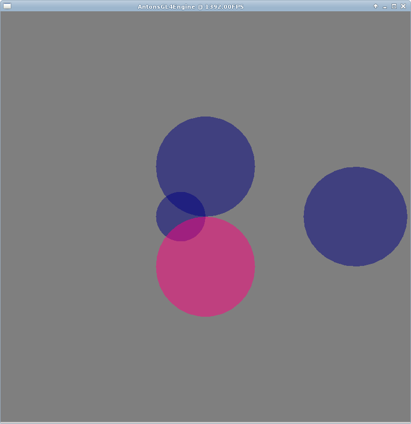
Probably the easiest method for selecting objects in a 3d scene. If you know a bounding radius, and centre point, of each object then we have the definition of its sphere. This might not be the best method to use for large, or irregularly shaped objects, which will have very large spheres that might overlap with smaller objects nearby.
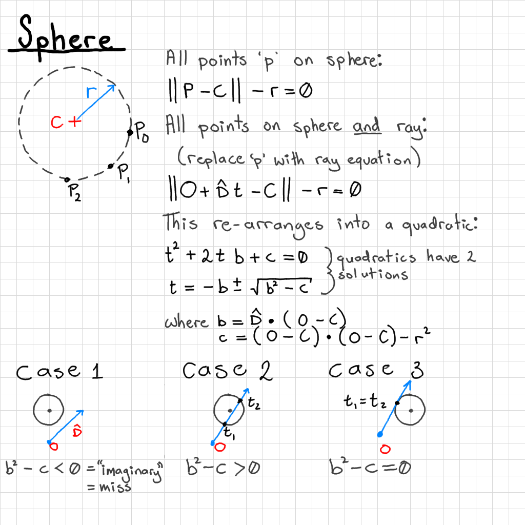
We can actually get 2 output intersections from a ray-sphere intersection because the ray can hit both the back and the front of the sphere. In this case we need to check for the closest intersection (smallest value of t). The ray can also miss the sphere, hit the very edge of the sphere (both t values are the same), or be cast from inside the sphere (one t value is negative).
Be sure to check the b^2 - c term before evaluating the expensive square root operator. If you miss the sphere entirely you will not get a sensible result for t. It is also possible that the ray will be cast from in front of or inside of the sphere, so you will need to check that your t values are positive.
You probably won't need to unless you're doing a lot of clicking on spheres, but you can reduce the cost of this algorithm by adding a few checks before getting to the square root. Compare squared distances between the ray origin and the sphere centre. You can project this as a 2d distance along the ray direction (dot product) and compare the end point's squared distance to the sphere origin (use Pythagoras' theorem) with the squared radius.
Generally, if you want to draw on a shape (e.g. dragging boxes) then ray-casting is a good choice. If you want inaccuracy i.e. letting the user click in the general area of a fiddly little mesh to select it then ray-casting is a good choice. If you want accuracy then you're almost certainly better off using a colour-based picking method, which has the cost of one extra rendering pass, rather than 1-5 ray casts per selectable object in the scene.
You can do ray versus axis-aligned box intersection, which is quite commonly used. An object in the world is considered to have a bounding box, rather than a bounding sphere. This has the weakness that irregularly shaped, rotating objects will create gigantic boxes, but it is quite easy to work out the extents, and use these to validate a set of ray-plane intersections.
If your shapes are actually boxes, or you want the box to rotate with the object inside, then you can do a ray versus oriented box intersection in much the same way. A few optimised methods exist (Haines "Essential Ray Tracing Algorithms", Chapter 2). I haven't had occasion to use this "in the wild".
Ray versus triangle collisions will let you determine exactly where on a more complex mesh that you have clicked on. If you need this much accuracy, you are probably better off using the colour buffer method and getting a pixel-correct method. It might be useful for things like shooting games where you want put a bullet hole image in an exact location though. I haven't found a good reason to use this one in a while either. Before testing several different surfaces of a complex object, it's generally advised to do a ray versus bounding sphere test first - no point testing all of the triangles if the ray has missed the whole object!